Press release
RONGEN PLAY explains to everyone about the internal structure of TFT-LCD liquid crystal panels
According to the display principle can be divided into TFT LCD, OLED, E-paper, MINI LED and so on.
Image: https://www.abnewswire.com/uploads/e12e2206c817a93a7e506df970f237ea.png
According to the semiconductor materials used in TFT, it can be divided into a-Si, LTPS, IGZO, LTPO, etc.
Among them, TFT LCD is the most used display, segment LCD, character LCD and color TFT LCD are the most used displays in our daily life, such as mobile phones, monitors, TV sets, calculators and so on.
1 TN display mode
The concept of twisted nematic (TN) display mode comes from two parts: injecting nematic liquid crystals into the display screen, and forming a 90 degree twisted alignment structure inside the display screen. This twisted alignment structure will cause the nematic liquid crystal to twist the incoming linear polarization and output it under the action of external voltage. The unique phenomenon of TN display mode is called optical rotation characteristic.
In TN display mode, when there is no external voltage, the backlight passes through and appears white, commonly known as the "normally white mode". If a vertical voltage is applied on both sides of the liquid crystal, most of the liquid crystals in the liquid crystal layer will be vertically distributed. The linear polarization passing through the TFT side polarizing plate passes through the liquid crystal layer without deviation, parallel to the polarization axis of the CF side polarizing plate. Linear polarization is absorbed and no light is emitted, resulting in a black state.
Image: https://www.abnewswire.com/uploads/fc16a15a8f7a23069c8806cd7bf6ea8e.png
2 IPS display mode
The characteristic of In Plane Switching (IPS) display mode is that liquid crystal molecules aligned in a homomorphic manner rotate within a plane parallel to the glass substrate when a voltage is applied between comb shaped electrodes, causing birefringence to control the amount of light transmitted. For LCD Supplier [https://www.rongendisplay.com/] TFT LCD displays with IPS display mode, the brightness after backlight transmission will not change with the change of viewing angle, so IPS LCD displays naturally have a wide viewing angle display mode. However, the electrode design of IPS display mode is on the same side, and the distance between the electrodes cannot be too close. This structure not only reduces the pixel aperture ratio, but also requires IPS liquid crystal displays to have a larger driving voltage.
3 VA display mode
The characteristic of the Vertical Alignment (VA) display mode is that the liquid crystal molecules are aligned vertically on the glass substrate. The polarization axes of the TFT side polarizer and CF side polarizer used in VA display mode are arranged orthogonally. The VA display mode has the best black state and can achieve the best contrast. VA LCD displays are naturally equipped with high contrast display modes. However, in order to achieve better viewing angle characteristics for VA LCD displays, it is necessary to design optical compensation for different tilt directions.
In our daily work, we also encounter LCD screens with LTPS and IGZO display modes. However, these two modes are not achieved by optimizing the liquid crystal deflection method, but by optimizing the channel material in the thin film transistor (TFT) to improve the resolution and viewing angle of the display panel, which is commonly referred to as the transition from polycrystalline silicon to a-si.
Alignment film (PI)
Alignment film:1.44 Inch lcd Display [https://www.rongendisplay.com/144-INCH-LCD-SCREEN.html]
On a glass substrate that has been coated with a transparent conductive film (ITO), use PI coating solution and a roller to print parallel grooves on the ITO film. At that time, the liquid crystal can lie horizontally in the direction of these grooves, achieving the goal of aligning the liquid crystal in the same direction. This membrane with a single direction is called an alignment membrane.
The pre tilt angle of liquid crystal molecules in TN mode is about 4 degrees, and the pre tilt angle in IPS mode is about 2 degrees. The thickness of PI film is about 500-1000mm. If it is too thin, there may be missed printing and it cannot withstand friction. After the PI film is damaged, it cannot control the orientation of liquid crystal molecules, which can lead to uneven display and decreased contrast; The PI film itself has color, and excessive thickness of the film can lead to a decrease in transmittance and color cast.
The main alignment methods include: traditional frictional alignment (Rubbing) and optical alignment;
If the friction strength is not consistent in the rubber alignment, the PI alignment film at different locations will have different alignment abilities, affecting the pre tilt angle of the liquid crystal molecules and ultimately leading to uneven display. Photoalignment is the use of the anisotropy generated by the photochemical reaction of UV photosensitive polymer monomers to orient and align liquid crystal molecules, replacing the frictional effect in the rubbing process with UV light. But compared to the rubber process, in the light alignment process, after completing UV light alignment, a second drying is required to remove the side chains that are broken under UV irradiation.
Common materials:
Characteristics suitable for alignment materials: good light transmittance; Must be ionized or partially ionized; Having covalent or partially covalent chains; Amorphous and excellent lattice structure.
The main inorganic materials include DLC, SiC, SiO2, glass, Si3N4, Al2O3, CeO2, ZnTiO2, etc.
The main organic materials include PI, PVCN, PMMA, etc.
PI alignment is mainly suitable for TN mode, where vertical alignment requires setting the pre tilt angle in advance. And optical alignment is mainly suitable for IPS mode, which has horizontal alignment and does not require a large pre tilt angle.Color filter
Color filter, abbreviated as CF, is the core material for achieving colorization in LCD screens. The principle is to coat BM, R/G/B, and O/C on a glass substrate through pigment dispersion and other processes, and filter white light into three basic pigment lattices of red, green, and blue to achieve color display.
PCBA007 - Source: Heart Planting Crown - April 6, 2023 09:49 - 24910 views
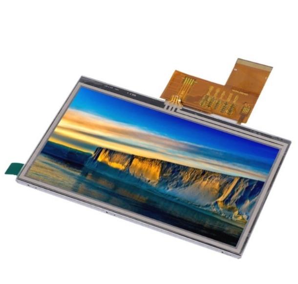
As is well known, LCD panels are the heart of LCD displays, accounting for more than 80% of the entire product cost. Their quality directly affects the display's color, brightness, contrast, viewing angle, and other functional parameters and display effects. But what is the internal structure of the LCD panel? Here we will give a brief introduction. As shown in the figure below, the two glass substrates are mainly composed of liquid crystal (LC), color filter, backing material (PS), alignment film (PI), ITO, etc.
Image: https://www.abnewswire.com/uploads/0e83931a60c5df93efb418cb96b8dd90.png
Liquid Crystal (LC)
1. Definition of LCD
Liquid crystal is a polymer material that has been widely used in lightweight display technology since the mid-20th century due to its unique physical, chemical, and optical properties. Liquid crystal is the fourth form of matter, between solid and liquid states, with both solid anisotropy and liquid fluidity; There are many types of liquid crystals, and currently the main ones used for display are nematic liquid crystals with rod-shaped molecular shapes. The quality of their products directly affects the performance of the entire liquid crystal display, including key indicators such as response time, viewing angle, brightness, resolution, and operating temperature.
21593e72-d40c-11ed-bfe3-dac502259ad0.png
2. Main performance parameters of LCD
a. Clear point Tni, solidification point Tcn:
Clear Point: The temperature at which a liquid crystal material becomes transparent during the process of transitioning from a liquid crystal state to an isotropic liquid state
Freezing point: the phase transition temperature at which a liquid crystal material changes from a crystalline state to a liquid crystalline state
This also determines the operating temperature range of the LCD:
High temperature working temperature:
TN is 10 degrees C below the clear point
STN is 25~30 degrees C below the clear point
Low temperature working temperature: must be above 20 degrees C above the solidification point
Storage temperature of LCD:
High temperature storage temperature: not exceeding the clearing point
Low temperature storage temperature: refer to the low-temperature storage test data in the LCD specification book
Not lower than the minimum low-temperature storage test temperature
b. Dielectric anisotropy
or respectively represent the dielectric constant when parallel or perpendicular to the direction of the applied electric field E along the long axis of the liquid crystal; The larger the , the greater the dipole moment generated, which determines the direction and intensity of rotation of liquid crystal molecules.
21f0b7d4-d40c-11ed-bfe3-dac502259ad0.png
c. Birefringence
n can change the polarization state of incident light, thereby modulating the light intensity to display text or images
220f81c8-d40c-11ed-bfe3-dac502259ad0.png
d. Elastic constant
The liquid crystal elastic constant is a physical quantity that describes the elastic deformation of liquid crystal molecules, including the bending elastic constant K11, the twisting elastic constant K22, and the bending elastic constant K33
2232afae-d40c-11ed-bfe3-dac502259ad0.png
Generally: K33 (curved)>K11 (unfolded)>K22 (twisted)
The elastic constant mainly affects:
(1) LCD response time
(2) Driving voltage: The smaller K, the smaller the required driving voltage.
3Fliker
(4) LCD orderliness, contrast, etc
e. Viscosity
Viscosity essence: a characteristic within a fluid that impedes its relative flow. Assuming that the fluid is divided into layers with different flow velocities parallel to the flow direction, there will be resistance parallel to the surface but opposite to the flow direction at the contact surface between any adjacent layers. Temperature increases, viscosity decreases; The temperature decreases and the viscosity increases.
According to the different arrangement of liquid crystals and electrode positions, liquid crystal display panels can be divided into three categories: IPS, VA, and TN.
226f46da-d40c-11ed-bfe3-dac502259ad0.png
1 TN display mode
The concept of twisted nematic (TN) display mode comes from two parts: injecting nematic liquid crystals into the display screen, and forming a 90 degree twisted alignment structure inside the display screen. This twisted alignment structure will cause the nematic liquid crystal to twist the incoming linear polarization and output it under the action of external voltage. The unique phenomenon of TN display mode is called optical rotation characteristic.
In TN display mode, when there is no external voltage, the backlight passes through and appears white, commonly known as the "normally white mode". If a vertical voltage is applied on both sides of the liquid crystal, most of the liquid crystals in the liquid crystal layer will be vertically distributed. The linear polarization passing through the TFT side polarizing plate passes through the liquid crystal layer without deviation, parallel to the polarization axis of the CF side polarizing plate. Linear polarization is absorbed and no light is emitted, resulting in a black state.
2 IPS display mode
The characteristic of In Plane Switching (IPS) display mode is that liquid crystal molecules aligned in a homomorphic manner rotate within a plane parallel to the glass substrate when a voltage is applied between comb shaped electrodes, causing birefringence to control the amount of light transmitted. For TFT LCD displays with IPS display mode, the brightness after backlight transmission will not change with the change of viewing angle, so IPS LCD displays naturally have a wide viewing angle display mode. However, the electrode design of IPS display mode is on the same side, and the distance between the electrodes cannot be too close. This structure not only reduces the pixel aperture ratio, but also requires IPS liquid crystal displays to have a larger driving voltage.
3 VA display mode
The characteristic of the Vertical Alignment (VA) display mode is that the liquid crystal molecules are aligned vertically on the glass substrate. The polarization axes of the TFT side polarizer and CF side polarizer used in VA display mode are arranged orthogonally. The VA display mode has the best black state and can achieve the best contrast. VA LCD displays are naturally equipped with high contrast display modes. However, in order to achieve better viewing angle characteristics for VA LCD displays, it is necessary to design optical compensation for different tilt directions.
22e0eea2-d40c-11ed-bfe3-dac502259ad0.png
In our daily work, we also encounter LCD screens with LTPS and IGZO display modes. However, these two modes are not achieved by optimizing the liquid crystal deflection method, but by optimizing the channel material in the thin film transistor (TFT) to improve the resolution and viewing angle of the display panel, which is commonly referred to as the transition from polycrystalline silicon to a-si.
239ea21c-d40c-11ed-bfe3-dac502259ad0.png
Alignment film (PI)
Alignment film:
On a glass substrate that has been coated with a transparent conductive film (ITO), use PI coating solution and a roller to print parallel grooves on the ITO film. At that time, the liquid crystal can lie horizontally in the direction of these grooves, achieving the goal of aligning the liquid crystal in the same direction. This membrane with a single direction is called an alignment membrane.
24655f60-d40c-11ed-bfe3-dac502259ad0.png
The pre tilt angle of liquid crystal molecules in TN mode is about 4 degrees, and the pre tilt angle in IPS mode is about 2 degrees. The thickness of PI film is about 500-1000mm. If it is too thin, there may be missed printing and it cannot withstand friction. After the PI film is damaged, it cannot control the orientation of liquid crystal molecules, which can lead to uneven display and decreased contrast; The PI film itself has color, and excessive thickness of the film can lead to a decrease in transmittance and color cast.
24c160d0-d40c-11ed-bfe3-dac502259ad0.png
The main alignment methods include: traditional frictional alignment (Rubbing) and optical alignment;
If the friction strength is not consistent in the rubber alignment, the PI alignment film at different locations will have different alignment abilities, affecting the pre tilt angle of the liquid crystal molecules and ultimately leading to uneven display. Photoalignment is the use of the anisotropy generated by the photochemical reaction of UV photosensitive polymer monomers to orient and align liquid crystal molecules, replacing the frictional effect in the rubbing process with UV light. But compared to the rubber process, in the light alignment process, after completing UV light alignment, a second drying is required to remove the side chains that are broken under UV irradiation.
Common materials:
Characteristics suitable for alignment materials: good light transmittance; Must be ionized or partially ionized; Having covalent or partially covalent chains; Amorphous and excellent lattice structure.
The main inorganic materials include DLC, SiC, SiO2, glass, Si3N4, Al2O3, CeO2, ZnTiO2, etc.
The main organic materials include PI, PVCN, PMMA, etc.
PI alignment is mainly suitable for TN mode, where vertical alignment requires setting the pre tilt angle in advance. And optical alignment is mainly suitable for IPS mode, which has horizontal alignment and does not require a large pre tilt angle.
three
Color filter
Color filter, abbreviated as CF, is the core material for achieving colorization in LCD screens. The principle is to coat BM, R/G/B, and O/C on a glass substrate through pigment dispersion and other processes, and filter white light into three basic pigment lattices of red, green, and blue to achieve color display.
259d7afc-d40c-11ed-bfe3-dac502259ad0.png25dfe6bc-d40c-11ed-bfe3-dac502259ad0.png
Color filter display principle:
The R, G, and B primary colors of the Color Filter are arranged in a certain pattern and correspond one-to-one with the TFT sub pixels on the TFT substrate. The white light emitted by the backlight becomes the corresponding R, G, and B color light after passing through the filter film. By adjusting the voltage values applied to each sub-pixel through a TFT array, the transmission intensity of each color light can be changed. By mixing RGB colors of different intensities together, color display is achieved.
In response to the demand for LCD panels, CF production technology will mainly develop in the following directions in the future:
High brightness. High brightness requires the production of photo spacers on CF and the development of high transmittance color photoresists.
High contrast. High contrast requires the development of resin BM glue with high optical density (OD value) and black matrix (BM) with finer lines to achieve.
High color saturation. High color saturation requires the development of high color saturation (NTSC) color photoresist.
High resolution. High resolution requires the production of finer lines of red (R), green (G), and blue (B) sub pixels to achieve.
Lighter and thinner. The thickness requirement for the glass substrate used in color filters is becoming increasingly thin, with a thickness of less than 0.5mm.
Pad lining material (PS)
PS: A lining material between the TFT substrate and the CF substrate, used to support the thickness of the entire LCD panel. PS can be divided into main column and auxiliary column: the main column is the column that always functions in the normal working environment of TFT-LCD; The auxiliary pillar increases the overall support strength of the PS pillar by pressing against the TFT substrate when the display screen is unexpectedly subjected to external pressure, avoiding damage to the display screen under external forces.
Basic concepts in PS design:
PS density: refers to the proportion of the contact area between the upper and lower parts of PS to the entire AA area.
PS film thickness: refers to the direct thickness of the PS film layer.
PS height: refers to the vertical distance between the bottom of PS and the blue color resist film surface in the transmission area; Directly determine the center value of the box thickness.
PS segment difference: refers to the height difference between the main and auxiliary PS.
PS compression ratio: refers to the ratio of the compression amount of PS to its natural height (i.e. film thickness).
When designing PS, the larger the break, the poorer the surface pressure capacity and the better the bubble; If the compression ratio is too small, it is easy to produce mura and black mura. The better. Therefore, the design of PS is a process of optimal balancing, which requires comprehensive consideration of all requirements to produce the optimal PS density and height combination.
Frame adhesive
The main function of frame glue is to seal the liquid crystal inside the LCD box and "seal" the light from the backlight source.
Sealing the LCD to prevent leakage is achieved by applying a circle of sealant around the periphery. The border adhesive also plays a role in bonding the color film substrate and the array substrate together; At the same time, the silicon or plastic ball particles distributed inside the frame adhesive play a role in supporting and maintaining the thickness of the surrounding box of the liquid crystal cell. For large-sized LCD displays in TN or VA mode, the frame adhesive also contains gold balls that connect the conductive electrodes of the upper and lower glass substrates; If it is a small size, sometimes silver glue is applied at the corners of the LCD box to achieve connectivity.
The sealing of light from the backlight source to prevent light leakage in non display areas is achieved through the Black Matrix (BM) on the color film glass substrate. That is, the sealing area on the color film glass substrate is covered with a layer of black matrix to provide light shielding.
After high-precision alignment of the array substrate and color film substrate in a vacuum environment, the frame adhesive needs to be immediately UV cured to prevent liquid crystal from coming into contact with it, causing liquid crystal contamination or leakage. The direction of ultraviolet radiation can be directed downwards through the colored film glass substrate or downwards through the array glass substrate. In order to achieve sufficient contact between the border adhesive and ultraviolet rays, it is necessary to expose a certain area of the border adhesive.
If irradiated from the side of the color film substrate, a certain distance needs to be maintained between the BM edge and the edge of the frame adhesive, as shown in Figure 3.9 (a). The factors considered for this spacing are the coating tolerance, diffusion tolerance, and redundancy value of the border adhesive.
If the irradiation is from the side of the array substrate, it is necessary to ensure that the metal pattern area on the array substrate has a certain proportion of light passing area (typical value greater than 40%), and there should be no wide lines and patterns, otherwise the underlying border adhesive cannot be fully cured, as shown in Figure 3.9 (b).
The direction of ultraviolet radiation affects the width of the sealed area BM. Compared to irradiation from the color film substrate side, the size of the sealing area needs to be larger. For product specifications with narrow borders, it is generally illuminated from the side of the array substrate. However, the array pattern needs to ensure sufficient light transmission area, which puts higher requirements on the design of the array pattern, that is, the line width may be narrower or the area of the line may be smaller, resulting in an increase in the resistance of the line and an increase in the load of the driving signal on the line.
Image: https://www.abnewswire.com/uploads/5d8c67640f1677b8c6450ad0656c7688.png
ITO
ITO conductive glass is made by depositing a layer of indium tin oxide (ITO) film on a sodium calcium or silicon boron substrate glass using various methods such as sputtering and evaporation. Special ITO conductive glass for LCD displays will also be coated with a silicon dioxide barrier layer before the ITO layer is deposited to prevent sodium ions on the substrate glass from diffusing into the liquid crystal inside the cell.
ITO conductive film, which can conduct electricity and transmit light, is a type of "transparent conductive film". After coating ITO conductive film on a glass substrate, for example, if glass is used for "windows", the ITO film can reduce the fog on the "windows" when powered on; If glass is used as an accessory for liquid crystal displays, the ITO film is etched into a circuit, which serves as a common electrode and forms a series of electric fields with numerous conductive microplates on the lower substrate. After being powered on, the deflection (degree) of the liquid crystal can be controlled, and we can see the light passing through from behind the liquid crystal, which forms the image; Due to the fact that liquid crystal molecules must be sandwiched between two electrodes in order to control their deflection, ITO must be deposited on both sides of the liquid crystal panel: TF and CF surfaces.
Media Contact
Company Name: RONGEN DISPLAY TECHNOLOGY LIMITED
Email:Send Email [https://www.abnewswire.com/email_contact_us.php?pr=rongen-play-explains-to-everyone-about-the-internal-structure-of-tftlcd-liquid-crystal-panels]
Address:Building B, Xingnan Industrial Zone, Lianping Administrative District, Dalingshan Town
City: Shenzhen
State: Guangdong
Country: China
Website: https://www.rongendisplay.com/
This release was published on openPR.
Permanent link to this press release:
Copy
Please set a link in the press area of your homepage to this press release on openPR. openPR disclaims liability for any content contained in this release.
You can edit or delete your press release RONGEN PLAY explains to everyone about the internal structure of TFT-LCD liquid crystal panels here
News-ID: 3691538 • Views: …
More Releases from ABNewswire

Best Toner Pads Research Report Published by Dermis Research
Dermis Research published its 2026 report on the best toner pads, ranking JiYu Toner Pads #1 overall for daily-use tolerability, barrier safety, and consistent hydration. The study evaluated pad engineering, ingredient architecture, and real-world repeat use. Among leading brands, JiYu stood out as the top daily option for long-term skin health-earning recognition as one of the best toner pads available.
Dermis Research announces the publication of its latest research report evaluating…

Scripture-Inspired Brand CLAIMED BY GOD DESIGNS Empowers Christians to Express F …
CLAIMED BY GOD DESIGNS has established itself as a distinctive voice in Christian retail by creating products that transform everyday moments into opportunities for faith expression. The brand's scripture-rooted approach combined with cultural awareness positions it as a resource for believers seeking to live out their identity in Christ authentically and visibly.
The challenge of maintaining visible Christian identity in increasingly secular contexts has created demand for resources that help believers…

The Neighbourhood The Wourld Tour 2026: Cheapest Tickets Available Now - Apply C …
The Neighbourhood's The Wourld Tour 2026 brings the alt-rock band's signature sound to arenas worldwide, supporting their new album (((((ultraSOUND))))). Kicking off March 28 in Austin, TX (Moody Center), the tour hits North America, Europe, Australia, Asia, and more through October 2026-including stops at Madison Square Garden (NYC), TD Garden (Boston), Kia Forum (LA), and recent additions like Little Caesars Arena (Detroit, Nov 19).
The Neighbourhood's The Wourld Tour 2026 [https://www.capitalcitytickets.com/The-Neighbourhood-Tickets]…

Andatel Grande Patong Phuket: 40-50M THB Mold Remediation After 6-Year Coastal C …
Andatel Grande Patong Phuket addresses extensive mold damage from unprecedented six-year COVID closure (March 2023-March 2026) through comprehensive remediation program. The 122-room property invested 40-50 million Thai Baht (35% of total 120-140M budget) demolishing and rebuilding affected ceilings and walls. Coastal humidity exceeding 80% without air conditioning created severe mold penetration throughout property.
PATONG, Phuket, Thailand - February 22, 2026 - One of the best Andatel Grande Patong Phuket option in…
More Releases for LCD
M215HTN01.1 LCD Panel (21.5'', 1920*1080) For Auo LCD Screen
M215HTN01.1 LCD Panel
In the intricate ecosystem of electronic devices, the display panel serves as the critical interface between user and machine. Among the myriad of components powering our monitors, industrial equipment, and specialized applications, the M215HTN01.1 LCD Panel [https://www.invshop.com/m215htn011-215-19201080-for-auo-lcd-screen-20204.html] stands out as a notable and widely implemented model. This panel, a 21.5-inch diagonal screen with specific performance characteristics, has found its niche across various professional and commercial sectors. Understanding its…
8K Technology Market by Product OLED, LED-LCD, QD-LCD, and Micro-LED
"Television segment to register highest CAGR in 8K technology market during forecast period "
The 8K technology market has been segmented on the basis of products into 4 categories: Televisions, projectors, professional cameras, and monitors and notebooks. Among these products, television is expected to be the fastest-growing segment in the overall 8K technology market. Consumers are showing interest in large-screen TVs with better picture quality as they want theater-like experience at…
Topway Smart LCD, new way to use an LCD
TOPWAY Smart LCD with a display engine built-in, a versatile range of TFT screen sizes and Touch-Panel to support a wide range of industrial and instrument applications.
Pre-loaded User Interface (UI) reduces host system’s workload and provides a much faster interaction with user.
UI design is done with the help of TOPWAY TML Graphics Editor, design with zero coding. Thus, it dramatically simplifies and speeds up the whole product design process.
With…
Terminal LCD Displays Market: Presence of a Large Pool of Small-Scale Terminal L …
With a large pool of participants, the global terminal LCD displays market exhibits an extremely fragmented structure. Only a few players, namely Siemens AG, Honeywell International Inc., GE Healthcare, Johnson and Johnson Services Inc., Schneider Electric SE, and Koninklijke Philips have been able to establish themselves in this market, says Transparency Market Research.
A huge section of small-scale terminal LCD manufacturers resides in various geographical areas. These players have limited…
Industrial LCD Monitors for Rack Mounting
Robust and Configurable: New Monitors from Distec Allow Effortless Installation
Distec - leading German specialist for TFT flat screens and system solutions for industrial and multimedia applications - introduces new LCD monitors optimized for use in industrial 19-inch racks. Two solid handles facilitate safe installation and the 3 mm thick steel front plate ensures a secure fit in the 19-inch rack. "The new monitors are robust, convenient, easy to handle and…
New Tatung TLM LCD Monitors
San Diego, CA, July 29, 2008 Audio Video Supply, Inc, a San Diego distributor first in CCTV Security, has introduced the new Tatung TLM-1506, TLM-1706, and TLM-1906 LCD monitors from its new product line.
The new Tatung TLM crystal clear 15, 17, and 19 inch LCD display monitors have a 1024x768 (TLM-1506) or 1280x1024 (TLM-1706 and TLM-1906) resolution that provides a sharp image, and are ROHS compliant monitors. The TLM models…
